I have recently found couple of posts (for example, this and this) on the net about generating VGA signals using just CPU. All those posts talk
about generating 640x480 VGA video signals using Arduino.
I have decided to try to generate VGA signals using Raspberry PI 3. I have
read that you can actually get the VGA output from the RPI without much problems, since it has that feature
built in the Broadcom SoC. However, I
didn't want to use the built in feature; I wanted to generate signals myself.
It proved to be quite difficult. First I tried the lowest possible level
library, under the Raspbian OS:
// Set GPIO pins to output
INP_GPIO(VIDEO); // must use INP_GPIO before we can use OUT_GPIO
OUT_GPIO(VIDEO);
INP_GPIO(H_SYNC); // must use INP_GPIO before we can use OUT_GPIO
OUT_GPIO(H_SYNC);
INP_GPIO(V_SYNC); // must use INP_GPIO before we can use OUT_GPIO
OUT_GPIO(V_SYNC);
vSyncLow();
hSyncLow();
vgaOff();
nsleep(99999999);
while(1) {
line = 0;
vSyncLow();
while(line < 600){
//2.2uS Back Porch
delayMicroseconds(2);
//20uS Color Data
vgaOn(); //High
delayMicroseconds(10); // 1uS
//Red Color Low
vgaOff(); //Low
delayMicroseconds(10); // 1uS
//1uS Front Porch
delayMicroseconds(1); // 1uS
line++;
//3.2uS Horizontal Sync
hSyncHigh(); //HSYNC High
delayMicroseconds(3);
hSyncLow(); //HSYNC Low
//26.4uS Total
}
//Clear the counter
line=0;
//VSYNC High
vSyncHigh();
//4 Lines Of VSYNC
while(line < 4){
//2.2uS Back Porch
delayMicroseconds(2);
//20 uS Of Color Data
delayMicroseconds(20);// 20uS
//1uS Front Porch
delayMicroseconds(1); // 1uS
line++;
//HSYNC for 3.2uS
hSyncHigh(); //High
delayMicroseconds(3);
hSyncLow(); //Low
//26.4uS Total
}
//Clear the counter
line = 0;
//VSYNC Low
vSyncLow();
//22 Lines Of Vertical Back Porch + 1 Line Of Front Porch
while(line < 22){
//2.2uS Back Porch
delayMicroseconds(2);
//20uS Color Data
delayMicroseconds(20);// 20uS
//1uS Front Porch
delayMicroseconds(1); // 1uS
line++;
//HSYNC for 3.2uS
hSyncHigh(); //High
delayMicroseconds(3);
hSyncLow(); //Low
//26.4uS Total
}
}
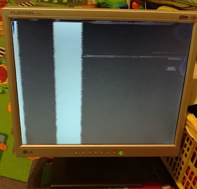
The result was this:
The monitor has some physical damage, but that is not the problem. The
problem is the bad synchronization. The timing is critical. Since the pixel frequency is approx. 25MHz,
the time for a single pixel is 40 nanoseconds. In the picture, it is obvious that the lines do not start
at the same time, which means that the horizontal sync pulses do not start at the precise time. They
miss their time for couple of hundred of nano seconds.
OK, this could be due to the multitasking in the Linux OS. So, I moved to
the bare metal programming. I have found a nice bare metal library on the github, here:
Author did a great job of making nice, readable examples. I have modified
one of his examples and made a VGA signal generator using the built in interrupt generator, which is
triggered every 3 microseconds:
// clear pending irq
*ARMTIMER_ACQ = 1;
//*TIMER_BASE = 2;
//printf("Inside dbg_main, counter: %d ", counter);
if (counter == 0) {
GPIO_SET(V_SYNC);
GPIO_SET(H_SYNC);
GPIO_SET(VIDEO);
} else
if (counter == 1) {
GPIO_CLR(H_SYNC);
GPIO_CLR(VIDEO);
} else
if ((counter % 8) == 0) {
GPIO_SET(H_SYNC);
GPIO_SET(VIDEO);
} else
if ((counter % 8) == 1) {
GPIO_CLR(VIDEO);
GPIO_CLR(H_SYNC);
}
if (counter == 17) {
GPIO_CLR(V_SYNC);
}
counter++;
if (counter == 4700) {
counter = 0;
}
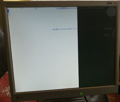
However, the picture was not much better:
The timing is a bit better, but still horizontal sync pulses manage to
miss the right time to fire.
I did all of this while waiting for the DE0-NANO FPGA board, which I
choose to play with in order to generate VGA signals. When it finally arrived, I was able to properly
generate VGA signals:
Then I have added the color and some text (top
left corner):
Damage on the LCD is visible here, but it is OK for the development.
Here is the Altera DE0-NANO FPGA board:
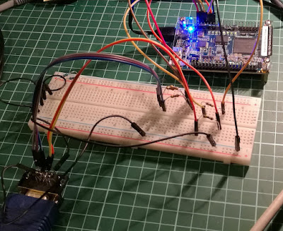
I have purchased a female VGA connector and connected GPIO pins from the
board to the connector:
- GPIO_R -> 68Ohm -> VGA_R
- GPIO_G -> 68Ohm -> VGA_G
- GPIO_B -> 68Ohm -> VGA_B
- GPIO_HS -> 470Ohm -> VGA_HORIZONTAL_SYNC
- GPIO_VS -> 470Ohm -> VGA_VERTICAL_SYNC
I have found various values for the resistors on various sites (from
direct connections, to 68 Ohms, 100Ohms, 500 Ohms, etc.), but this schematics works for me.
The Verilog code is quite simple. I have recycled the FizzBuzz example made by Ken Shirriff:
//////////// CLOCK //////////
input CLOCK_50, // this is 50MHz clock
//////////// KEY //////////
input KEY, // reset key (one of two onboard keys)
//////////// GPIO //////////
output reg r,
output reg g,
output reg b,
output wire hs,
output wire vs
);
//=======================================================
// REG/WIRE declarations
//=======================================================
reg clk25; // 25MHz signal (clk divided by 2)
reg newframe;
reg newline;
reg [9:0] x;
reg [9:0] y;
wire valid;
reg [7:0] xx;
reg [7:0] yy;
reg [7:0] framebuffer [9:0]; // 10 bytes text-based framebuffer
wire [6:0] counter;
wire [7:0] pixels; // Pixels making up one row of the character
//////////// GPIO //////////
output reg r,
output reg g,
output reg b,
output wire hs,
output wire vs
);
//=======================================================
// REG/WIRE declarations
//=======================================================
reg clk25; // 25MHz signal (clk divided by 2)
reg newframe;
reg newline;
reg [9:0] x;
reg [9:0] y;
wire valid;
reg [7:0] xx;
reg [7:0] yy;
reg [7:0] framebuffer [9:0];
wire [6:0] counter;
wire [7:0] pixels; // Pixels making up one row of the character
// Structural coding
//=======================================================
initial begin
framebuffer[0] = "0";
framebuffer[1] = "1";
framebuffer[2] = "2";
framebuffer[3] = "3";
framebuffer[4] = "A";
framebuffer[5] = "a";
framebuffer[6] = "B";
framebuffer[7] = "b";
framebuffer[8] = "8";
framebuffer[9] = "9";
end
// Character generator
chars chars_1(
.char(framebuffer[counter]),
.rownum(y[2:0]),
.pixels(pixels)
);
assign hs = x < (640 + 16) || x >= (640 + 16 + 96);
assign vs = y < (480 + 10) || y >= (480 + 10 + 2);
assign valid = (x < 640) && (y < 480);
assign counter = (valid)?(x >> 3):0;
always @(posedge CLOCK_50) begin
newframe <= 0;
newline <= 0;
if (!KEY) begin
x <= 10'b0;
y <= 10'b0;
clk25 <= 1'b0;
newframe <= 1;
newline <= 1;
end
else begin
clk25 <= ~clk25;
if (clk25 == 1'b1) begin
if (x < 10'd799) begin
x <= x + 1'b1;
end
else begin
x <= 10'b0;
newline <= 1;
if (y < 10'd524) begin
y <= y + 1'b1;
end
else begin
y <= 10'b0;
newframe <= 1;
end
end
end
end
if (valid) begin
if (x < 80 && y < 8) begin
r <= pixels[7 - (x & 7)];
g <= pixels[7 - (x & 7)];
b <= pixels[7 - (x & 7)];
end
else begin
r <= (x < 213) ? 1 : 0;
g <= (x >= 213 && x < 426) ? 1 : 0;
b <= (x >= 426) ? 1 : 0;
end
end
else begin
// blanking -> no pixels
r <= 0;
g <= 0;
b <= 0;
end
end
endmodule
Verilog programming is not simple. It has a steep learning curve. The
other problem can be a long compile time in the Quartus II IDE. For a bit more complex code than this
VGA project, the compile time easily exceeds couple of minutes. I have solved this problem by installing
the Icarus Verilog software, which compiles the Verilog code in a fraction of a second. This is due to
the fact that the Icarus Verilog is not intended to deploy the Verilog code to the actual hardware -
instead, it is intended for the simulation only. This way, I am able to produce the running and correct
code quickly, and then I can copy that code into the Quartus II IDE, build the project, and deploy it to
the real hardware.


