Added PS/2 keyboard to the FPGA Computer
This is a follow-up of the FPGA computer post.
I have added a keyboard port to the FPGA Computer. The port is PS/2 because it is easier to work with the PS/2 than with the USB HID protocol. The final look is here (you will recognize the purple PS/2 keyboard connector):
I have added a keyboard port to the FPGA Computer. The port is PS/2 because it is easier to work with the PS/2 than with the USB HID protocol. The final look is here (you will recognize the purple PS/2 keyboard connector):

Now the
board has three connectors: PS/2, VGA and UART.
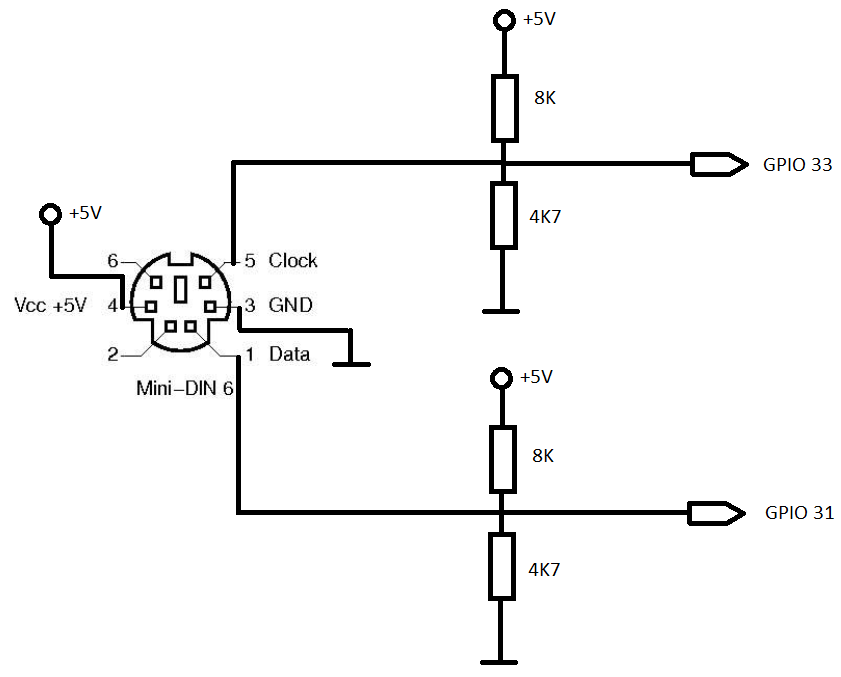
PS/2 connector is connected to the GPIO ports of the DE0-NANO board:
- Data is connected to the GPIO31 (PIN_D11) port
- Clock is connected to the GPIO33 (PIN_B12) port.
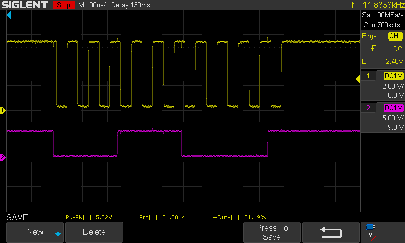
The communication between keyboard and computer is a clocked serial. Clock
pulses appear on the Clock pin, while data is on the Data pin, synchronized with the Clock on the
falling edge. There is one start bit, one parity bit and one stop bit. Here are oscilloscope snapshots
of the "A" key being pressed (and then released):
The waveform below is the make code of the "A" key
(1C hex)
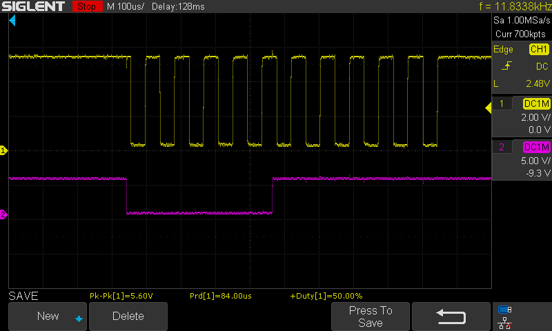
The waveform below is the first byte of the
"A" break code (F0 hex)
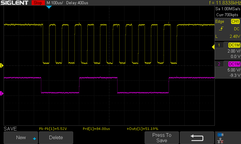
The waveform below is the second byte of the
"A" break code (1C hex)
Keyboards work by sending the make and the break codes for each key. Make
code is sent when the key is pressed, while the break code is sent when the key is released. For
example, when we press and then release the "A" key, we get the following sequence:
1C F0
1CThis could be interpreted as: A pressed (1C), A released (F0 1C)
Unfortunately, it is all not that simple. First of all, if you quickly press A and C, one after another, you will get the following sequence:
1C 1B F0 1B F0 1C
This could be interpreted as: make code of "A", make code of "S", break code of "S" and break code of "A".
When you press Shift + A, you will get the following sequence:
12 1C F0 1C F0 12
Shift pressed, A pressed, A released, Shift released
When you press A for a long time (autorepeat will occur):
1C 1C 1C 1C 1C F0 1C
A pressed, A pressed, A pressed, A pressed, A pressed, A released (F0 1C)
To make things more complicated, extended key codes (both make and break) have been introduced, for some keys. For example, the Cursor Down (Arrow Down) key produces the following sequence:
E0 72 E0 F0 72
Cursor down pressed (E0 72), Cursor down released (E0 F0 72).
And so on... All this makes parsing a bit complicated, but eventually you will be able to figure it out.
The next step was to add the support for the keyboard within the FPGA Computer.
Introducing the keyboard interrupt
I have introduced a new interrupt for the keyboard - the IRQ#2. This
IRQ is triggered when a byte from PS/2 keyboard arrives. The CPU then jumps to the address of 24
decimal, where the raw PS/2 keyboard handling routine should be. Actually, at that address should be
one JUMP instruction which will jump to the handling routine.
In the main computer module, I have instantiated the PS/2 module:
// ####################################
// PS/2 keyboard instance
// ####################################
wire [7:0] ps2_data;
wire ps2_received;
reg [7:0] ps2_data_r;
ps2_read ps2(
CLOCK_50,
reset,
gpio0[31], // Input
pin - PS/2 data line
gpio0[33], // Input
pin - PS/2 clock line
ps2_data, // here we
will receive a character
ps2_received // if something came from PS/2, this goes
high
);
Then I have detected the byte being received from the PS/2 module and
triggered the IRQ:
always @ (posedge CLOCK_50) begin
// ######### IRQ2 -
keyboard ######
if (ps2_received)
begin
ps2_data_r <=
ps2_data;
// if we have received a
byte from
// the keyboard, we will
trigger the IRQ#2
irq[2] <=
1'b1;
end
...
In the cpu.v module, I have added a support for the new interrupt:
if (irq_r[2]) begin
`ifdef DEBUG
LED[7] <= 1;
$display("3.1 JUMP TO
IRQ #2 SERVICE");
`endif
pc <= 16'd24;
addr <=
16'd12;
end
; set the IRQ handler for keyboard to our own IRQ handler
mov r0, 1 ; JUMP instruction opcode
mov r1, IRQ2_ADDR ; IRQ#2 vector address
st [r1], r0
mov r0, irq_triggered
mov r1, IRQ2_ADDR + 2
st [r1], r0
Since this is raw PS/2 handling, the programmer must write the complete make/break code handling. I have done that in this example.
Unfortunately, the code is quite long since it has to deal with the raw PS/2 protocol. The code demonstrates parsing the raw PS/2 protocol and it looks like those vintage screen editors:

How to use the keyboard? First of all, two
callbacks should be registered - one for the key pressed, and the other one for the key released:
mov r0, 1 ; JUMP instruction opcode
mov r1, KEY_PRESSED_HANDLER_ADDR
st [r1], r0
mov r0, pressed ; key pressed routine address
mov r1, KEY_PRESSED_HANDLER_ADDR + 2
st [r1], r0
mov r0, 1 ; JUMP instruction opcode
mov r1, KEY_RELEASED_HANDLER_ADDR
st [r1], r0
mov r0, released ; key released routine address
mov r1, KEY_RELEASED_HANDLER_ADDR + 2
st [r1], r0
Both callbacks will then need to obtain the
virtual key code of the key pressed (or released) by reading from the location 48
(VIRTUAL_KEY_ADDR):
pressed:
ld r0, [VIRTUAL_KEY_ADDR]
cmp r0, VK_F1
...
released:
ld r1, [VIRTUAL_KEY_ADDR]
...
What is the Virtual Key Code? It is a
number assigned to each key, so all the programs would get the same number when a key is pressed, or
released. In the code above, VK_F1 is the constant assigned to the F1 key, so the programmer can
determine if the F1 was pressed by writing cmp r0, VK_F1.
Then, if needed, programmer can call the
vk_to_char function which translates a virtual key to the actual character, if possible
(not all keys produce characters; F1 key does not produce character, for example):
;
###############################
; r1 = function vk_to_char(r1)
; translates virtual key to
character
; if shift is pressed, does the
uppercase
;
###############################
vk_to_char:
push r0
push r2
...
Conclusion
Most examples for keyboard support on the net use PS/2 keyboards, since
USB HID protocol is quite complex and PS/2 isn't. I went the same path. I have couple of spare
keyboards, some of them are PS/2, so I have soldered the PS/2 female connector and those four resistors
from the schematics above. From that point on, everything was programming - a little bit of Verilog
programming, and much more of assembler programming.