One Day Build - Digital Clock
I have recently decided to make a digital table clock. The design I chose
consists of three important parts:
- ESP32,
- 7-segment four digits display with no special driver, and
- DS3231 real time clock.
The code is on github.
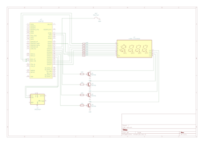
Here is the schematics:
// GPIO ports for LEDs
// Dot A B C D E F G
int LEDS[] = {2, 32, 33, 25, 26, 27, 14, 12};
// GPIO ports for digits
int DIGITS[] = { 18, 19, 17, 16 };
Next I defined the matrix of LEDs for digit representation:
int DIGIT_MATRIX[][7] = {
// A B C D E F G
{HIGH, HIGH, HIGH, HIGH, HIGH, HIGH, LOW}, // 0
{LOW, HIGH, HIGH, LOW, LOW, LOW, LOW}, // 1
{HIGH, HIGH, LOW, HIGH, HIGH, LOW, HIGH}, // 2
{HIGH, HIGH, HIGH, HIGH, LOW, LOW, HIGH}, // 3
{LOW, HIGH, HIGH, LOW, LOW, HIGH, HIGH}, // 4
{HIGH, LOW, HIGH, HIGH, LOW, HIGH, HIGH}, // 5
{HIGH, LOW, HIGH, HIGH, HIGH, HIGH, HIGH}, // 6
{HIGH, HIGH, HIGH, LOW, LOW, LOW, LOW}, // 7
{HIGH, HIGH, HIGH, HIGH, HIGH, HIGH, HIGH}, // 8
{HIGH, HIGH, HIGH, HIGH, LOW, HIGH, HIGH}, // 9
{LOW, LOW, LOW, LOW, LOW, LOW, HIGH}, // '-' index is 10
{LOW, LOW, LOW, LOW, LOW, LOW, LOW} // BLANK index is 11
};
- ESP32,
- 7-segment four digits display with no special driver, and
- DS3231 real time clock.
The code is on github.
Since ESP32 has WiFi module, I used it for two purposes: to obtain the correct
time once a day (and synchronize the DS3231 to that correct time), and to obtain the temperature information
from my weather server, so I could get the outside temperature with a single button press.
I purchased the most simple 7-segment display which has 12 pins: 8 pins for
the digit segment selection and 4 pins for the digit selection. Those four pins are common cathodes of the
LEDs making each digit - that is why it has four common cathodes - for those four digits.
DS3231 is a good RTC with temperature compensation and optional battery
(CR2032) to work without external power source.
Here is the schematics:
Driving the 7-segment four digit display is quite interesting. You cannot
illuminate more than one digit in time. This means that you need to illuminate the first digit, then the
second, then the third, and the fourth, and then to do it all again, fast. Thanks to our vision persistence,
we get the impression that all four digits are illuminated.
If you look at the schematics, you will notice that the digit definition is
done using GPIO pins 32, 33, 25, 26, 27, 14, 12, and 2, which turn on/off segments a, b, c, d, e, f, g, and
dot. That would only set the corresponding LEDs input to high or low voltage, but would not illuminate them
(the circuit would not be closed until the common cathode is connected to the ground). To choose which digit
will be illuminated (to have the common cathode connected to the ground), I used GPIO pins 16, 17, 18, and
19. Logical one (3.3V) on those GPIO pins would turn on the corresponding transistor and it would connect
the common cathode of the connected digit to the ground.
// GPIO ports for LEDs
// Dot A B C D E F G
int LEDS[] = {2, 32, 33, 25, 26, 27, 14, 12};
// GPIO ports for digits
int DIGITS[] = { 18, 19, 17, 16 };
Next I defined the matrix of LEDs for digit representation:
int DIGIT_MATRIX[][7] = {
// A B C D E F G
{HIGH, HIGH, HIGH, HIGH, HIGH, HIGH, LOW}, // 0
{LOW, HIGH, HIGH, LOW, LOW, LOW, LOW}, // 1
{HIGH, HIGH, LOW, HIGH, HIGH, LOW, HIGH}, // 2
{HIGH, HIGH, HIGH, HIGH, LOW, LOW, HIGH}, // 3
{LOW, HIGH, HIGH, LOW, LOW, HIGH, HIGH}, // 4
{HIGH, LOW, HIGH, HIGH, LOW, HIGH, HIGH}, // 5
{HIGH, LOW, HIGH, HIGH, HIGH, HIGH, HIGH}, // 6
{HIGH, HIGH, HIGH, LOW, LOW, LOW, LOW}, // 7
{HIGH, HIGH, HIGH, HIGH, HIGH, HIGH, HIGH}, // 8
{HIGH, HIGH, HIGH, HIGH, LOW, HIGH, HIGH}, // 9
{LOW, LOW, LOW, LOW, LOW, LOW, HIGH}, // '-' index is 10
{LOW, LOW, LOW, LOW, LOW, LOW, LOW} // BLANK index is 11
};
To display a digit, you need to call two following functions:
void displayDigit(int value)
{
int j, k;
for (j = 1; j < 8; j++)
{
digitalWrite(LEDS[j], (DIGIT_MATRIX[value][j-1]));
}
}
The function above will set the corresponding LEDs for the given digit, but
will not illuminate anything, since we haven't selected which one of the four digits should be activated. To
do so, we need the following function:
void activateDigit(int digit)
{
switch(digit)
{
case 0:
digitalWrite(DIGITS[0], HIGH);
digitalWrite(DIGITS[1], LOW);
digitalWrite(DIGITS[2], LOW);
digitalWrite(DIGITS[3], LOW);
digitalWrite(LEDS[0], LOW);
break;
case 1:
digitalWrite(DIGITS[0], LOW);
digitalWrite(DIGITS[1], HIGH);
digitalWrite(DIGITS[2], LOW);
digitalWrite(DIGITS[3], LOW);
digitalWrite(LEDS[0], LOW);
break;
case 2:
digitalWrite(DIGITS[0], LOW);
digitalWrite(DIGITS[1], LOW);
digitalWrite(DIGITS[2], HIGH);
digitalWrite(DIGITS[3], LOW);
digitalWrite(LEDS[0], LOW);
break;
case 3:
digitalWrite(DIGITS[0], LOW);
digitalWrite(DIGITS[1], LOW);
digitalWrite(DIGITS[2], LOW);
digitalWrite(DIGITS[3], HIGH);
digitalWrite(LEDS[0], LOW);
break;
default:
digitalWrite(DIGITS[0], LOW);
digitalWrite(DIGITS[1], LOW);
digitalWrite(DIGITS[2], LOW);
digitalWrite(DIGITS[3], LOW);
digitalWrite(LEDS[0], LOW);
}
}
So, displaying time from the RTC module looks like this. First we read the
time from the RTC (once in two seconds):
void read_time()
{
DateTime now = rtc.now();
int hour = now.hour();
int minute = now.minute();
hour_1 = hour / 10;
hour_2 = hour % 10;
minute_1 = minute / 10;
minute_2 = minute % 10;
}
We break up the time into four digits: hour_1, hour_2,
minute_1, and minute_2. Then, in the main loop, we display that time by showing each digit
quickly (each digit is illuminated one millisecond):
void loop()
{
switch(counter)
{
case 0:
displayDigit(hour_1);
break;
case 1:
displayDigit(hour_2);
break;
case 2:
displayDigit(minute_1);
break;
case 3:
displayDigit(minute_2);
break;
}
activateDigit(counter);
counter++;
if (counter == 4)
{
counter = 0;
}
// duty cycle adjustment for the LED brightness
delayMicroseconds(500);
activateDigit(-1);
delayMicroseconds(500);
}
As you can see, the time is fetched from the RTC outside of the main loop. I
have done that because obtaining the time from the RTC inside the loop might screw up the LED illumination,
since the main loop would be blocked while reading the time from the RTC. To avoid that, I have used the
ESP32 task to do the RTC reading. In the setup function, I have created a task for obtaining time:
// create a task that will be executed in the Task1code() function,
// with priority 1 and executed on core 0
// this task will get time from RTC every two seconds
xTaskCreatePinnedToCore(
Task1code, /* Task function. */
"Task1", /* name of task. */
10000, /* Stack size of task */
NULL, /* parameter of the task */
1, /* priority of the task */
&Task1, /* Task handle */
1); /* pin task to core 1 */
Task1code() is a task function which is executed in parallel with
the loop() function. Task1 is a task handler variable, which holds a handler for this task:
TaskHandle_t Task1;
void Task1code( void * pvParameters ){
for(;;){
read_time();
delay(2000);
}
}
This task is executed as an infinite loop. It obtains the time from the
RTC and then sleeps for two seconds. Then it does all of it again.
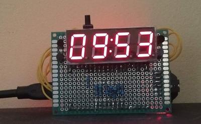
This is the time displayed by the clock:
Getting the outside temperature from my weather server was an interesting
task. When I press the button, the clock would have to connect to the weather server, send the HTTP request
for the temperature info, receive the HTTP response, parse it and display the outside temperature on the
clock, instead of current time.
const char root_ca[]= {
// here comes the certificate in bytes...
};
http.begin("https://myserver/status", root_ca);
int httpCode = http.GET();
// httpCode will be negative on error
if(httpCode > 0) {
// got the response from the server
if(httpCode == HTTP_CODE_OK)
{
String payload = http.getString();
String t = parse_response(payload);
int temp = t.toInt();
if (t.startsWith("-"))
{
hour_2 = 10; // "-" sign
temp = -temp;
} else
{
hour_2 = 11; // BLANK character
}
hour_1 = 11;
minute_1 = temp / 10;
minute_2 = temp % 10;
}
} else {
Serial.printf("[HTTP] GET... failed, error: %s\n",
http.errorToString(httpCode).c_str());
}
http.end();
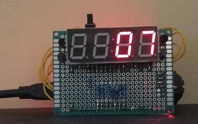
The clock would display the temperature outside:
When I press the button again, the clock will display the internal
temperature, obtained from the RTC. RTC has the temperature sensor built in so that it can compensate the
time drift caused by the temperature change. That sensor info is exposed to the programmer:
float int_temp = rtc.getTemperature();
int temp = (int)int_temp;
temp = temp -2;
hour_1 = 11;
hour_2 = 11;
minute_1 = temp / 10;
minute_2 = temp % 10;
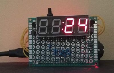
Here is the temperature inside:
How is this clock initialized when powered up? How is this clock
synchronized to the precise time? I used the WiFi connection to connect the clock to the time server:
http.begin("https://myserver/time", root_ca);
int httpCode = http.GET();
// httpCode will be negative on error
if(httpCode > 0) {
// got the response from the server
if(httpCode == HTTP_CODE_OK)
{
String payload = http.getString();
parse_time(payload);
rtc.adjust(DateTime(year, month, day, hour, minute, second));
}
} else {
Serial.printf("[HTTP] GET... failed, error: %s\n",
http.errorToString(httpCode).c_str());
}
http.end();
The code above does not synchronize the clock to the exactly precise time
(because of the delay), but it is good enough for me.
Conclusion
This table clock build was very interesting. The main challenge was to make
all the digits show properly on the 7-segment display. When I mastered that, the rest was a breeze: getting
the temperature from the weather server and showing the internal room temperature.


Comments
Comments powered by Disqus