Yet another one day build of a digital clock

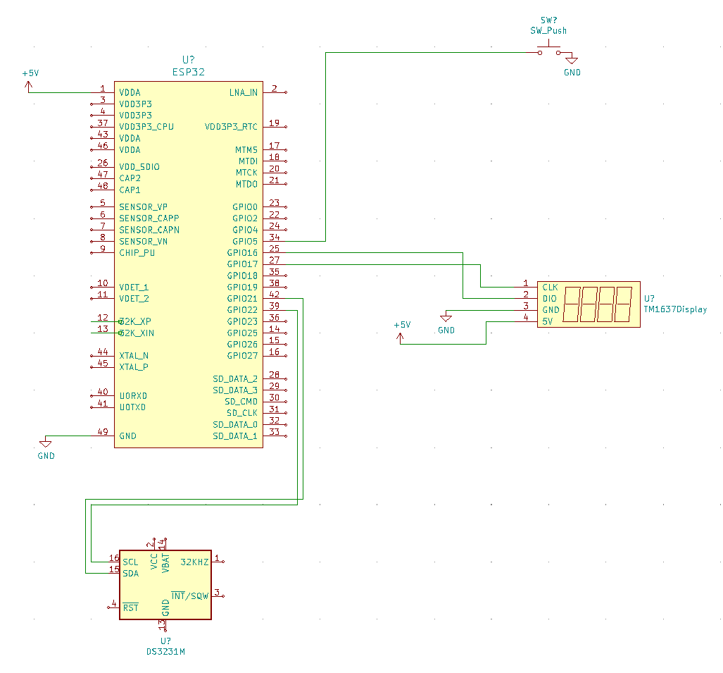
So, what is the difference this time? I have used TM1637 four-digit, 
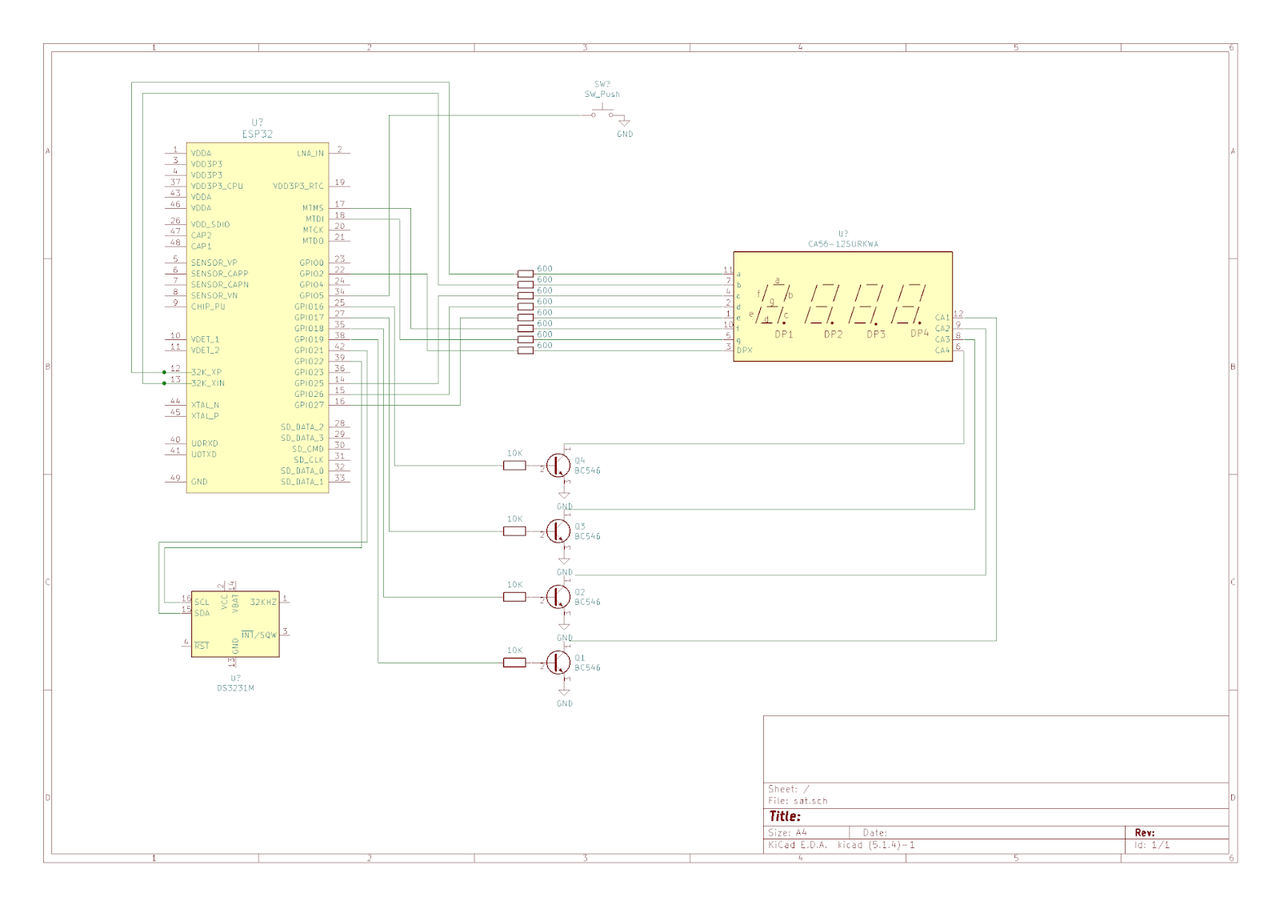
seven-segment display, instead of driverlesss display. The difference is in the number of components. Instead of having twelve resistors and four transistors to drive the 7-segment display, now I have a single display with the built-in driver.

The code is on github.
Here is the schematics:

Read more…

Another One Day Build - Big Digital Clock

Welcome to another digital clock build. This time I have made a big digital clock for my friend. The clock was made using programmable LED strip, cut into small pieces which would act as segments in a big 7-segment digit.

The code is on github.

Programmable LED strip

This is a very nice thing - you can set any color to the individual LED bulb on the strip:

Read more…

One Day Build - Digital Clock

I have recently decided to make a digital table clock. The design I chose consists of three important parts:
- ESP32,
- 7-segment four digits display with no special driver, and
- DS3231 real time clock.

The code is on github.

Since ESP32 has WiFi module, I used it for two purposes: to obtain the correct time once a day (and synchronize the DS3231 to that correct time), and to obtain the temperature information from my weather server, so I could get the outside temperature with a single button press.

I purchased the most simple 7-segment display which has 12 pins: 8 pins for the digit segment selection and 4 pins for the digit selection. Those four pins are common cathodes of the LEDs making each digit - that is why it has four common cathodes - for those four digits.

DS3231 is a good RTC with temperature compensation and optional battery (CR2032) to work without external power source.

Here is the schematics:


Read more…

Bench power supply

I have purchased a kit for bench supply from the AliExpress. The kit can be obtained for less than 10$, so you "only" need the rest of the stuff (case, better potentiometers, voltmeter, ampermeter, connectors, switches, etc.). I have purchased my kit from aliexpress (click on the image below):

Read more…

Fan control on the Raspberry Pi 4

I have recently purchased Raspberry Pi 4. It goes quite hot when working (even in idle), so I had to obtain a cooler. I have got one with big aluminum heat sink, and two small fans. They are meant to be connected to 5V and to work all the time. I didn't like that so I have decided to make a fan control.

The easiest way I could find was on this video:
https://www.youtube.com/watch?v=Pw1kSS_FIKk

The idea is quite simple: use one MOSFET to control the fan. I have connected the fan connector to the drain and GPIO pin to the gate and it looks like this:

The schematics of the circuit.

Read more…

Flashing DE0-NANO FPGA board and using DEV_CLRn reset functionality

In this post I am going to talk about programming DE0-NANO FPGA board two ways:
1. temporary programming, meaning that the design will not survive powering off, and
2. permanently storing (flashing) the design, so it will survive power off.

I will also address the idea of a mega-reset using the DEV_CLRn feature at the bottom of this post.

Disclamer: You are doing all of this at your own risk. I am not responsible for any problem caused by these examples. To prevent problems, check the documentation of your DE0-NANO to see if you have the same type of Programmer and EEPROM chips.

1. Temporary programming

Whenever you compile your design at the Quartus II IDE, you can send the design to the FPGA board via Programmer:

1. double click on the Program Device in the table:

Read more…

Added new VGA graphics mode

This is a followup of my original post.

FPGA computer has got a new VGA mode: 640x480 in two colors. One byte of the video memory holds 8 pixels, each being 1 or 0 (white or black):

Pixel 7
Pixel 6
Pixel 5
Pixel 4
Pixel 3
Pixel 2
Pixel 1
Pixel 0

If you want to put four white and four black pixels at the top left corner of the screen (from the (0,0) to the (7,0) coordinates), you need to type:

mov.w r0, 0xF0
st.b [1024], r0

This mode is made out of existing VGA text mode, since it does almost all the job. The text mode shows characters made of 8x8 pixels on the 640x480 VGA screen. I have inserted additional Verilog code inside the text mode module, in a way that when the 640x480x2 mode is set, it shows the pixels, not the characters.

Read more…

The ultimate read-only file system on the SD card

This is a kind of follow-up of my previous post:
https://blog.vidakovic.xyz/posts/2019/01/read-only-file-system-on-raspberry-pi

I have recently stumbled upon this tool:
https://github.com/BertoldVdb/sdtool

I immediately forked it:
https://github.com/milanvidakovic/sdtool

The main idea behind this tool is to set one of the following command bits of the CSD register (very low level communication) of the SD card (via SPI interface):

  • TMP_WRITE_PROTECT - temporarily enable/disable write protection for the SD card,
  • PERM_WRITE_PROTECT - permanently enable write protection for the SD card (cannot be reversed).
The behavior of the temporary write protection is quite interesting: when you enable it, it will silently fail when writing to the SD card. In reality, it means that when you try to write to a file (or create a new file), you will not get any error, and you might even be able to read that file (probably because it was placed in the cache of the file system), but as soon as you reboot, you will see that there have not been any changes.

Read more…

FPGA computer boots from the SD card

FPGA computer boots now from the SD card

This is a followup of my original post.


The 32-bit FPGA computer now has a kind of a hard disk. ESP32 is used as a hard disk controller (I have designed the board to work with the Arduino as well - you can see the empty socket for the Arduino to the right of the ESP32), while the SD card is used as a kind of a hard disk.


Read more…